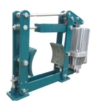
1. Product Positioning
The SBD-C is a normally-closed, fail-safe hydraulic disc brake designed for installation on the low-speed shaft (or drum shaft) of equipment. Its primary functions are safety braking, emergency braking, and static holding.
It is not intended for frequent operational braking; rather, it serves as a "final safety lock."
In the event of a power loss, hydraulic pressure failure, or system malfunction, the brake engages automatically to prevent uncontrolled movement-such as the slipping of a load, the rolling of a vehicle, or unintended reverse rotation.
2. Core Operating Principle
Spring (disc spring) applied braking; hydraulically released.
|
status |
Hydraulic power unit |
disc spring |
Brake arm |
Result |
|---|---|---|---|---|
|
Normal/Power-off |
stress-free |
Release the elastic force |
Clamp the brake disc |
brake holding |
|
Release brake |
Pressure supply |
compressed |
Outer tension release / Retract and open outward |
release brake operation |
Operational Logic:
Hydraulic fluid enters the cylinder → Piston compresses the disc springs
Brake arms open → Friction pads disengage from the brake disc
Loss of hydraulic pressure/power → Disc springs expand → Pads clamp onto the disc from both sides
Braking torque is generated, locking the low-speed shaft
Fundamental Principle: The brake remains engaged without the need for electrical power; electrical or hydraulic power is used to "release" the brake-a design that adheres to the fail-safe principle.
3. Common Models and Specifications (SBD-C Series)
| model | Rated clamping force (kN) | Braking force (kN) | Operating hydraulic pressure (MPa) | Unilateral retraction distance (mm) | Oil volume at gate opening (ml) |
|---|---|---|---|---|---|
|
SBD250-C |
250 |
180 |
8 |
1~2 |
275 |
|
SBD365-C |
365 |
262 |
8 |
1~2 |
275 |
|
SBD425-C |
425 |
306 |
9.5 |
1~2 |
275 |
Applicable disc diameter: D ≥ 1800 mm
Friction coefficient: μ ≈ 0.35 (for design calculations)
Approximate formula for braking torque:
M ≈ μ × F × d₁
where d₁ ≈ D - 220 (mm), and F is the total clamping force
4. Key Application Scenarios
Large and medium-sized cranes: main hoisting mechanisms, and low-speed shafts for boom luffing/tilting
Port machinery: container cranes, ship loaders, and ship unloaders
Mining equipment: mine hoists, winches, and inclined belt conveyors
Cable cars, ropeways, and cable cranes
Specialized lifting equipment, such as foundry cranes
5. Key Advantages
Fail-safe: Automatically engages the brake upon loss of power or hydraulic pressure, providing high safety redundancy.
High Braking Force: Suitable for low-speed, high-torque applications and static locking under heavy loads.
Excellent Heat Dissipation: The disc-type design offers better temperature control compared to drum-type designs.
Replaceable Brake Pads: Includes wear-limit alerts; designed to prevent damage to the disc.
Rapid Response: Short engagement time, effectively preventing unintended movement (roll-back).
Monitorable: Status signals can be integrated into a PLC system for interlocking.